
2016-10-21 10:57:00
Continuing where I left off last time (replay attack using a remote), I wanted to see how easy it would be to mess with the sensors attached to the Kerui home alarm system that I'm assessing.
For starters, I assumed that each sensor would use the same HS1527 with a different set of data sent for various states. At least in the case of the magnet sensors, that assumption was correct. The bitstreams generated by one of the contacts are as follows:
As I proved last time, replaying any of these codes is trivial using an Arduino or similar equipment. Possible use cases for miscreants could include:
Going one step further I was wondering whether the simple 433Mhz transmitter for my Arduino would be capable of drowning out the professionally made magnet contacts. By using Suat Özgür's RC-Switch library again, I set the transmitter to continuously transmit a stream of ones. Basically, just shouting "AAAAAAAAAHHHHH!!!!!" down the 433MHz band.
Works like a charm, as you can see in the video below. Without the transmitter going, the panel hears the magnet contact just fine. Turning on the transmitter drowns out any of the signals sent by the contact.
kilala.nl tags: work, sysadmin,
View or add comments (curr. 0)
2016-10-05 08:23:00

Having come a long way in the RF-part of my current security project, I decided to dive into the hardware part of my research. The past few weeks have been spent with a loupe, my trusty multimeter, a soldering iron and some interesting hardware!
Cracking the shell of the Kerui G19 shows a pretty nice PCB! All ICs and components are on the backside, the front being dedicated to the buttons and the business end of the LCD panel. Opening the lid on the back immediately shows what look like unterminated service pins (two sets of'm), which is promising.
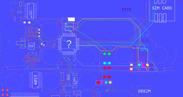
What's less promising, is that the main IC is completely unmarked. That makes identifying the processor very hard, until I can take a crack at the actual firmware. My initial guess was that it's some ARM7 derivative, because the central panel mostly acts like a dressed-down feature phone with Android. A few weeks later that guess feels very, very off and it's most likely something much simpler. As user PedroDaGr8 mentioned on my Reddit thread about the PCB:
"Most people would assume an ARM in this case. In reality, it might be ARM, PIC, AVR, MIPS, FPGA, CPLD, H78, etc. Any of these could fulfill this role and function. It often depends on what the programmer or programming team is familiar with. I have seen some designs from China before, that used a WAY OVERKILL Analog Devices Blackfin DSP processor as the core. Why? Because it was cheaper to use the guys they had that were proficient at programming in Blackfin than to hire new guys for this one product."
So until I can analyse the firmware, the CPU could be just about anything! :D
There are many great guides online, on the basics of hardware hacking, like DevTTYs0's "Reverse engineering serial ports" or Black Hills Security's "We can hardware hack, and you can too!". Feeling confident in their teachings I took to those service pins with my multimeter. Sadly, both rows of pins had an amount of pins that's not consistent with UART consoles but I didn't let that discourage me. Based on the measured voltages I hooked up my PL2303 UART-to-USB, to see if I could find anything useful.
No dice. Multiple pins provided output onto my Picocom console, often with interspersed Chinese unicode characters. But no pins would react to input and the output didn't look anything like a running OS or logging.
Between the lack of identification on the CPU and the lack of clear UART ports, it was time for hard work! I took a page from the book of Joffrey Czarny & Raphaël Rigo ("Reverse engineering hardware for software reversers", slide 11) and started mapping out all the components and traces on the PCB. Instead of using their "hobo method" with GIMP, I one-upped things by using the vector editor InkScape. My first few hours of work resulted in what you see above: a mapping of both sides of the PCB and the interconnections of most of the pins.
Thus I learned a few things:
Status for now: lots of rewarding work and I have a great SVG to show for it. And I've gotten to know my Arduino and PL2303 a bit better. But I haven't found anything that helps me identify an OS or a console port yet. I'll keep at it!!
kilala.nl tags: work, sysadmin,
View or add comments (curr. 2)
All content, with exception of "borrowed" blogpost images, or unless otherwise indicated, is copyright of Tess Sluijter. The character Kilala the cat-demon is copyright of Rumiko Takahashi and used here without permission.